Design
The goal was to create a high power LED bike light (some similar projects: a 3 LED mountain bike light, a whole series of evolving light designs or this simple and neat 3 LED light).
After discovering the BuckPuck LED driver has a 5V output and a dimmer control circuit, I decided to control it with a Picaxe microcontroller. The primary purpose of the microcontroller was to provide a battery level indicator of some sort. Secondary features would be to allow multiple brightness modes etc.
I couldn't find a simple battery level circuit or simple way to calculate the remaining capacity of a battery so decided instead to simply use the Picaxe to time the amount of time the light has been switched on and use this to determine when a recharge is required.
The aim is to discharge the batteries about 30% between each recharge. The circuit should draw a maximum of about 1A for the LED, and say 0.2A for the Picaxe and bargraph LEDs. Using 2400mAH batteries, and 100% efficiency, would give 2 hrs at 100% discharge. However the light will rarely be on at full power; assuming it's on at 30% power, a 30% discharge will therefore take about 2 hours... or so I'm guessing, it's much more complicated than that, but that'll do for now.
The controller will require two buttons to change up and down through the brightness modes, and one to test the battery level (i.e. display the timer value.) Two buttons are required to avoid having to cycle through all the modes to get back to the start, like all the stupid flashing LED tail lights require...
The pins for the buttons plus one output for the LED controller and one to drive the LED bargraph uses all 5 input/output pins on the Picaxe 08M.
One further feature was added, which is a "high beam" button. This will override the current mode from the Picaxe and put the LED on full power. This will be used to briefly illuminate dark parts of paths and to flash at cars that might not have seen me or have cut in front of me or something like that. Fortunately, this button does not need to be connected to the Picaxe, as there are no free pins.
Schematic
The Picaxe usese 3 standard input circuits. For the outputs, Pin2 is used for PWM output in the background to drive the LED controller. This will allow different brightnesses to be set by varying the duty cycle.
To drive the LED bargraph, the basic reference circuit from the LM3914 datasheet is used to measure the voltage over a resistor/capacitor circuit. The capacitor is charged via a PWM output from the picaxe. Varying the duty cycle allows the capacitor to charge to different levels which is reflected in the bargraph.
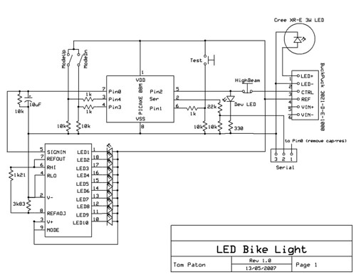
I added a fuse between the battery and the BuckPuck too, just in case. No idea if it's really needed...
Parts list
| Components | ||
|---|---|---|
| 1 | Cree XR-E 3W LED + 8° Lens + BuckPuck 3023-D-E-1000 Driver (datasheet) | (Cutter Electronics) |
| 1 | Picaxe 08M microcontroller | (Microzed) |
| 1 | LM3914 LED bargraph driver (datasheet) | (DSE) |
| 1 | 10 seg LED bargraph | (DSE) |
| 3 | 1k resistors | |
| 4 | 10k resistors | |
| 1 | 1k2 resistors | |
| 1 | 3k6 resistors | |
| 1 | 0k2 resistors | |
| 1 | 10uF 25V electrolitic capacitor | |
| Hardware | ||
| 1 | Plastic "Jiffy" box (30x54x83mm) | (DSE) |
| 1 | Veroboard (24 tracks x 18 holes) | (DSE) |
| 1 | Heatsink | (Jaycar) |
| 1 | 3.5mm mono plug + socket | (Jaycar) |
| 1 | SPDT rocker switch (on-off-on) | (Jaycar) |
| 1 | Push button (N/O) | (DSE) |
| 1 | Push button (N/C) | (DSE) |
| 1 | Fuse + Holder (M205 2A) | (Radioparts) |
| 1 | 8 Pin DIL socket | (DSE) |
| 1 | 18 Pin DIL socket | (DSE) |
| 1 | 20 Pin DIL socket (machine pin strip) | (DSE) |
| 2 | 4 AA battery holder | (Jaycar) |
| 2 | 9v Battery snaps | (DSE) |
| 8 | AA NiMH batteries (2400mAH) | (Jaycar) |
| 2 | velcro straps 12.5cm of hook + 12.5cm fuzz | (Spotlight) |
| 1 | inner tube rubber | |
| Materials | ||
| 1 | Arctic Silver Thermal Adhesive | (Mittoni) |
Note: The above suppliers are not necessarily where I got the part, just the first link I could find...
Software
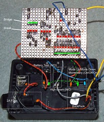
The above circuit was first layed out on a breadboard with a regular LED in place of the 3W Cree LED and using 4 AA batteries directly rather than via the BuckPuck.
Note that when I got the BuckPuck and LED, the 4 AA batteries were not sufficient to provide enough voltage from the Ref pin to switch the LED off. This was fixed by using all 8 AA batteries.
LED bargraph output calibration
After realising I had no real idea how to get the LM3914 input range to match the output from the Picaxe, or how to choose the right resistor/capacitor combination, it occurred to me that it didn't matter and the picaxe could be calibrated to output voltages that lit up the bargraph LEDs the right amount. Hooray for software!
The values output by the following program when each of the 10 LEDs lit up were written down and used in the final program.
symbol x = b0
symbol y = b1
symbol dot = b2

main:
 for x = 0 to 10
  dot = x
  gosub display_dot
 next x
 for x = 10 to 0 step -1
  dot = x
  gosub display_dot
 next x
 goto main


display_dot:
 lookup dot, (0, 89, 134, 156, 169, 177, 184, 190, 198, 207, 214), y

 pwm 1, y, 100

' pause 500

 return
Controller program
' 252 bytes program + 2 bytes data

' pins
symbol led_pin = 2
symbol dot_pin = 0
symbol test_btn = pin3
symbol modeUp_btn = pin4
symbol modeDn_btn = pin1

' variables
symbol mode = b0
symbol time = w4
symbol time_counter = w6

symbol dot = b1
symbol dot_duty = b2
symbol dot_cycles = b3

symbol led_period = b4
symbol led_duty = w5


' constants
symbol minMode = 0
symbol maxMode = 10
symbol flashMode = 9
symbol maxTime = 1200 ' minutes * 10
symbol dotTime = maxTime / 10
symbol time_interval = 1122 ' roughly 11215 ticks per minute

' data
eeprom 0, (0, 0) ' time as a word

' initialize
high led_pin

mode = 0
read 0, word time

' wakeup
gosub strobe

main:
 dot_cycles = 50

 time_counter = time_counter + 1
 if time_counter > time_interval then
  ' clock tick (4 bytes)
  high dot_pin
  high dot_pin
  low dot_pin

  time = time + 1
  goto write_time ' return to main
 endif

 if modeUp_btn = 1 and mode < maxMode then
  mode = mode + 1
  goto show_mode ' return to main
 endif
 if modeDn_btn = 1 and mode > minMode then
  mode = mode - 1
  goto show_mode ' return to main
 endif

 if test_btn = 1 then
  dot = time / dotTime max 10
  dot_cycles = 100
  gosub do_dot
  ' hold to reset (8 bytes per delay loop)
  if test_btn = 1 then
   gosub do_dot
   if test_btn = 1 then
    gosub strobe

    time = 0
    goto write_time ' return to main
   endif
  endif
 endif

 if mode >= flashMode then
  gosub do_mode
 endif

 goto main

write_time:
 write 0, word time
 time_counter = 0
 goto main

show_mode:
 gosub do_mode
 dot = mode
 gosub do_dot
 goto main

do_mode: ' high - led off, low - led on
 led_period = 255
 'led_duty = 4 - mode * 250
 lookup mode, (0, 1010, 980, 950, 900, 800, 600), led_duty
 select mode
  case 0 ' off
   led_period = 0
   high led_pin
'  case 1 ' dim 1
'   led_duty = 750
'  case 2 ' dim 2
'   led_duty = 500
'  case 3 ' dim 3
'   led_duty = 250
  case 8 ' full
   led_period = 0
   low led_pin
  case 9 ' dim short flash
   led_period = 0
   'low led_pin
   'pause 50
   pwm led_pin, 150, 10
   high led_pin
   pause 350
  case 10 ' long flash (17 bytes)
   led_period = 0
   low led_pin
   pause 100
   high led_pin
   pause 300
 endselect

 pwmout led_pin, led_period, led_duty

 return

do_dot:
 lookup dot, (0, 89, 134, 156, 169, 177, 184, 190, 198, 207, 214), dot_duty

 pwm dot_pin, dot_duty, dot_cycles
 low dot_pin

 return

strobe:
 dot_cycles = 10
 for dot = 1 to 10
  gosub do_dot
 next dot
 return
Some points to note:
- The time the light has been running in "minutes" is stored in the EEPROM memory of the Picaxe.
- Pressing the "test" button will display the current time on the bargraph using 1 LED for each 12 minutes (120 minutes total).
- Holding the "test" button for a few seconds will reset the timer. This will be used when freshly charged batteries are inserted.
- There are 8 brightness modes (plus "off") and two flash modes.
Timer calibration
The above controller flashes the bargraph briefly each 6 seconds or so. A few minutes worth of these flashes were counted and timed and the program adjusted so that the bargraph will reach 10 after approximately 120 minutes.
Construction
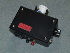
First, all the required holes were drilled in the box, and the aluminium lid was bent into shape to hold the LED and heatsink. The box lid was also shaped to fit the aluminium lid sticking out the side.
The spacers inside the box were cut down to lower the circuit board so there was enough room for the LED bargraph to stick out the top and the switches and BuckPuck to fit underneath.
The wires from the BuckPuck were soldered to the LED (with an extra wire joined to LED -ve output to become the ground for the circuit board.)
The LED was glued to the heatsink using the Arctic Silver epoxy, and when it was dry the heatsink and LED were glued to the aluminium lid.
The first version of the battery pack was put together at this stage too. This failed as the battery holders were made of Delrin which is ungluable... So, I drilled tiny holes in the two cases and "sewed" them together with fine jewellery or tie wire. An on/off switch was soldered to the battery wires and the socket assembled.
The circuit board layout was sketched out, the board cut to size and the tracks between the IC sockets cut. The sockets were then soldered in and the the resistors and capacitor soldered in too. The chopped off legs from the resistors were used as bridges between the +ve LED bargraph pins and the ground 10k resistor line. Some legs were also used to form some jumpers, with soldered in for others.
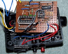
Next, I measured out the wire and soldered to the switches etc. and soldered in the BuckPuck and circuit board.
At this point, the circuit was tested and found to work (incredibly!) so the bottom of the circuit board was insulated with some electrical tape and the whole lot squeezed into the box.
A thin strip of inner tube rubber was added as a gasket on top of the aluminium lid to seal it in case of rain (which wasn't really considered in the design...)
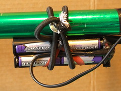
For the first test ride, the whole lot was attached to my bike with rubber bands and the batteries were lashed to the frame with an inner tube! I was very happy with the results so started working out a more permanent mounting mechanism.
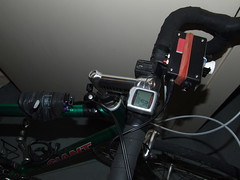
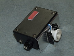
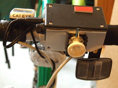
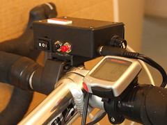
I removed the socket from my old Cateye light and bolted/Araldyted it to the box, which took care of mounting the light itself. It is adjustable/tiltable too which is a nice bonus.
Initially the batteries were mounted using an elastic strap, but this proved to be a little difficult to attach/remove with less than 3 hands and I dropped it breaking the damn thing. Because the battery holder can't be glued I had to start again with a different construction method.
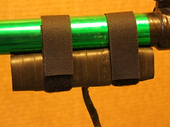
This time, the battery holders were "sewn" together using jewellery wire again and the whole lot held in a cradle made from inner tube rubber (helpfully sewn by Alison) that is velcroed to the bike.
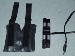
This looks quite professional and is a lot easier to take on and off!
Results
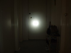
I'm extremly happy with the results, the LED is way too bright to look at and lights the road extremely well when on "full". Under normal conditions "mode 3" was quite sufficient to see the road.
The following image was taken by shining the light onto my door from about 3m away and photographing at 1/15 sec, f2.8, ISO100. The door has a slightly gloss paint, so the middle of the beam is being reflected back.
Some minor changes I would make:
- The "high beam" button really neads to be accessible without moving your hand to the light. I'm not sure how best to achieve this.
- A switch on the battery box would be useful (this was initially planned but died with the first battery box.)
- A "console light" to light up my speedo.
- Waterproof design!
- A future version may well use a proper battery capacity meter (such as this one for lead acid batteries or this one for R/C cars.)
5 comments:
You didn't tell me you had a blog you fucker!
Another future improvement: Use a proper power plug and socket, as that will reduce the risk of shorting out the current plug given there's no longer an off switch on the battery box.
I've retired this little project from use now, and posted about the new solution.
It worked well for over 3 years which is pretty good for something that if I recall correctly cost somewhere between $100-150 to build while comparable commercial systems were well over $500.
This is nice project, using LED light for bike. LED light last long than ordinary light and it's consume less energy than ordinary.
Par 20 LED Lightspar 20 LED Light
Your LED light making procedure very nice and i think your goal is achieved by making this high power LED bike light it will now help others. Keep posting such post.
Post a Comment