Tuesday, July 31, 2007

Picaxe breadboard adapter

A quick project to simplify Picaxe prototyping on my breadboard. The idea is to house the Picaxe chip (either an 08M or 14M) and "standard" serial interfacing circuit on a "breakout" board that can be easily plugged into the breadboard while providing easy access to the chip's pins.

  1. power input, about 5V, will be regulated by LM7805
  2. 3.5mm stereo serial socket
  3. serial mode selector, switches serial in between "pin 5" (program mode) and "pin 3" (control mode)
  4. power switch
  5. jumpers to allow isolating standard serial circuit to "override" via breadboard
  6. 14 pin socket
  7. header pins to provide 5V and 0V to "power rails" of breadboard
  8. header pins to connect Picaxe to breadboard


serial schematic


power schematic

For some unknown reason, I had to add an extra 10k resistor between leg 2 and ground (soldered on the underside of the pcb, not shown on schematic.)

The board works pretty much as I'd hoped. Unfortunately it is quite difficult to insert/remove from the breadboard so a future version would only have a single row of header pins. Another addition would be a DC socket to allow powering from a "wall wart" and I'd improve the layout a little to allow easier access to the switches.

Tuesday, July 24, 2007

Handlebar "Remote" for LED Bike Light

Changing modes and using the high-beam was awkward using the switches mounted on the original LED bikelight box, so I added a "remote" within easy reach of my thumb. This will make the high-beam more useful when approaching treacherous areas of paths that require more light but are exactly the places where you don't want to take your hands off the handlebars.

This uses a "rocker" navigation switch to change modes, pushing it switches on the high beam. The mode-up and down buttons are simply wired in in parallel with the existing mode rocker switch, however the high-beam was a bit trickier and uses a BD681 darlington pair transitor to "pull" the control signal to the BuckPuck to ground. This has the same effect as the existing NC push-button switch.

This was necessary because all three switches on the navigation switch share a common wire, the Picaxe software and circuit is expecting the switches to provide +5v, so it was easier to make the high-beam use a transistor to cut-out the control signal than rework the remainder of the circuit to pull the Picaxe pins to ground when the switches are pushed. If I was building this again, using ground as the common wire would be much simpler.

There was enough room on the existing pcb to solder in the transistor, resistor and wires from the navigation switch. That's one advantage of using proto-board over a printed pcb.

One further mod would be to have a capacitor attached to the BD681 some how so that a single push holds the high-beam on for say 5 seconds, but I couldn't figure out how to get that to work. Alternatively, putting in a flip-flop to toggle the high-beam on/off would work too, but there was definitely not enough space on the pcb for that option.

Friday, July 06, 2007

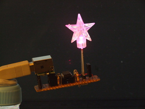
Ambient Email Notifier

Small project to provide email notification via an RGB LED hooked up to the USB port.

Uses a 4d-micro-USB module to provide power and RS232 to a Picaxe 08M controlling an RGB LED. Can control colour (seven colours: work email in red, newsletters in green, other in blue) and brightness by sending characters to the COM port, this is done by a Python script run every 10 minutes by Task Scheduler with an accompanying system tray icon to allow LED to be turned off again (see python gmail check in four lines of code, pySerial and pySystray).

The schematic is as simple as possible:

The relevant code (python and picaxe basic) is pretty self-evident, I will provide it if anyone is interested. Update: Another post has some code.